-
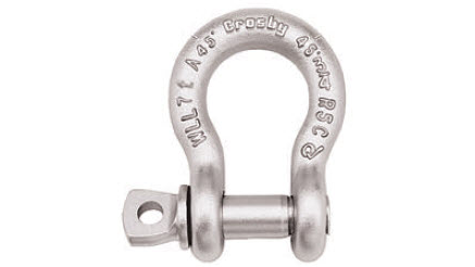
CROSBY: G209A SCREW PIN SHACKLE
2018-01-15 11:03:15FEATURES
• Capacities 2 thru 21 metric tons. Meets performance requirements of Grade
8 shackles
• Forged Alloy Steel – Quenched and Tempered, with alloy pins
• Working Load Limit permanently shown on every shackle
• Hot Dip Galvanized
• Shackles can be furnished proof tested with certificates to designated
standards
• Meets or exceeds all requirements of ASME B30.26 including identification,
ductility, design factor, proof load and temperature requirements. Import
antly, these shackles meet other critical performance requirements including
impact properties and material traceability, not addressed by ASME B30.26
Screw pin anchor shackles meet the performance requirements of
Federal Specification RR-C-271F Type IVA, Grade B, Class 2, except
for those provisions required of the contractor. For additional
information.Nominal
Size
(in.)
WLL
(T*)
STOCK NO.
UPC NO.
WEIGHT
(LBS.)
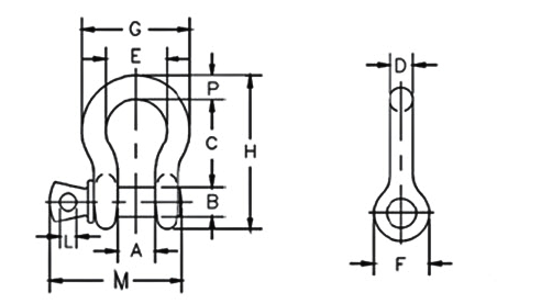
Dimensions (IN.)
TOLERANCE
(+ / -)
A
B
C
D
E
F
G
H
L
M
P
C
A
3/8
2
G209A3/8CS-5P
1017450
0.31
0.66
0.44
1.44
0.38
1.03
0.91
1.78
2.49
0.25
2.03
0.38
0.13
0.06
7/16
2-2/3
G209A7/16CS-5P
1017472
0.38
0.75
0.50
1.69
0.44
1.16
1.06
2.03
2.91
0.31
2.38
0.44
0.13
0.06
1/2
3-1/3
G209A1/2CS-5P
1017494
0.63
0.81
0.63
1.88
0.50
1.31
1.19
2.31
3.28
0.38
2.69
0.50
0.13
0.06
5/8
5
G209A5/8CS-5P
1017516
1.38
1.06
0.75
2.38
0.63
1.69
1.50
2.94
4.19
0.44
3.34
0.69
0.13
0.06
3/4
7
G209A3/4CS-5P
1017538
2.35
1.25
0.88
2.81
0.75
2.00
1.81
3.50
4.97
0.50
3.97
0.81
0.25
0.06
7/8
9-1/2
G209A7/8CS-5P
1017560
3.61
1.44
1.00
3.31
0.88
2.28
2.09
4.03
5.83
0.50
4.50
0.97
0.25
0.06
1
12-1/2
G209A1CS-5P
1017582
5.32
1.69
1.13
3.75
1.00
2.69
2.38
4.69
6.56
0.56
5.07
1.06
0.25
0.06
1-1/8
15
G209A11/8CS-5P
1017604
7.25
1.81
1.25
4.25
1.16
2.91
2.69
5.16
7.47
0.63
5.59
1.25
0.25
0.06
1-1/4
18
G209A11/4CS-5P
1017626
9.88
2.03
1.38
4.69
1.29
3.25
3.00
5.75
8.25
0.69
6.16
1.38
0.25
0.06
1-3/8
21
G209A13/8CS-5P
1017648
13.25
2.25
1.50
5.25
1.42
3.63
3.31
6.38
9.16
0.75
6.84
1.50
0.25
0.13
* Maximum Proof Load is 2 times the Working Load Limit. Minimum Ultimate Strength is 4.5 times the Working Load Limit. For Working Load Limit reduction due to side
loading applications
-